Tutorial
Toward SDN experiments
Software-defined networking has been the focus of a lot of attention in the network community for the last years. Without entering in the details of SDN, this tutorial show how you can deploy a topology where the network is managed in the SDN way.
SDN infrastructures can be deployed leveraging specific hardware or software components. Here we will focus on a software based infrastructure.
1 Using OpenFlow
1.1 Prerequisites
In order to perform the network interconnection, we will use OpenSWitch and in order to control the behavior of the network, we will use POX as an OpenFlow controller. In order to run OpenVSwitch inside the vnodes, it must also be installed on the pnodes.
To ease the installation, we will deploy the physical nodes with an environment that already contains OpenVSwitch. Its description can be found at the following place: http://public.nancy.grid5000.fr/~amerlin/kadeploy/jessie-x64-nfs-ovs.env.
We also need to have an LXC image that contains OpenVSwitch and POX. Such pre-built image can be found on Grid’5000 at the following place: http://public.nancy.grid5000.fr/~amerlin/distem/distem-fs-jessie-ovs.tar.gz.
Again you have to copy the distem image to your home:
1.2 Bridging virtual nodes in a L2 network
1.2.1 Platform deployment
For this experiment, we will use 4 nodes:
We assume that the reserved nodes are graphene-1,graphene-2,graphene-3,graphene-4
Those nodes will be deployed with:
Then, we install distem:
Note that we use the –enable-admin-network option. This allows to automatically create an isolated network containing all the virtual nodes of the platform. Thus, whatever the network configuration you have, all the vnodes will be reachable from the coordinator. Furthermore, the –vxlan-id is optional if only one Distem instance using VXLAN is launched on the same L2 network. Otherwise, each instance must have a different id.
We will create a topology with 4 virtual nodes, like in the following picture:
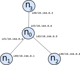
In this topology, we will create 3 isolated networks using the “VXLAN mode”, as follows:
- vnet1 that will contain n1 and n0
- vnet2 that will contain n2 and n0
- vnet3 that will contain n3 and n0
Here is the script of the platform:
#!/usr/bin/ruby
require 'distem'

img_ovs = "file:///home/USER/distem_img/distem-fs-jessie-ovs.tar.gz"
hosts = ARGV[0].split(',')
Distem.client { |cl|
  cl.vnetwork_create('vnet1', '10.144.128.0/24', {'network_type' => 'vxlan'})
  cl.vnetwork_create('vnet2', '10.144.128.0/24', {'network_type' => 'vxlan'})
  cl.vnetwork_create('vnet3', '10.144.128.0/24', {'network_type' => 'vxlan'})
  nodes = [ 'n0', 'n1', 'n2', 'n3' ]
  cl.vnode_create('n1',
                     {
                       'host' => hosts[1],
                       'vfilesystem' =>{'image' => img_ovs,'shared' => true},
                       'vifaces' => [
                                     {'name' => 'if0', 'vnetwork' => 'vnet1', 'address' => '10.144.128.1'},
                                    ]
                     })
  cl.vnode_create('n2',
                     {
                       'host' => hosts[2],
                       'vfilesystem' =>{'image' => img_ovs,'shared' => true},
                       'vifaces' => [
                                     {'name' => 'if0', 'vnetwork' => 'vnet2', 'address' => '10.144.128.2'},
                                    ]
                     })
  cl.vnode_create('n3',
                     {
                       'host' => hosts[3],
                       'vfilesystem' =>{'image' => img_ovs,'shared' => true},
                       'vifaces' => [
                                     {'name' => 'if0', 'vnetwork' => 'vnet3', 'address' => '10.144.128.3'},
                                    ]
                     })
  cl.vnode_create('n0',
                     {
                       'host' => hosts[0],
                       'vfilesystem' =>{'image' => img_ovs,'shared' => true},
                       'vifaces' => [
                                     {'name' => 'if1', 'vnetwork' => 'vnet1', 'address' => '10.144.128.4'},
                                     {'name' => 'if2', 'vnetwork' => 'vnet2', 'address' => '10.144.128.5'},
                                     {'name' => 'if3', 'vnetwork' => 'vnet3', 'address' => '10.144.128.6'}
                                    ]
                     })
  puts "Starting vnodes..."
  cl.vnodes_start(nodes)
  puts "Waiting for vnodes to be here..."
  sleep(30)
  ret = cl.wait_vnodes({'timeout' => 1200, 'port' => 22})
  if ret
    puts "Setting global /etc/hosts"
    cl.set_global_etchosts
  else
    puts "vnodes are unreachable"
  end
}
The script can be launched like that:
At this point, you can have a look at the /etc/hosts file on the coordinator. You will see that each vnode has a different entry for all the vnetworks it is attached to. Furthermore, you can see an additional entry for all the vnodes with a -adm suffix. This is related to the global administration network created with the previous distem-bootstrap execution. So, from the coordinator, you will be able to connect to any virtual nodes, like:
1.3 Bridging vnodes together
Since the vnodes n1, n2, and n3 are in different isolated networks, you will not be able to reach one node from another one. You can try for instance:
Thus, we will bridge n1, n2, and n3 into the same network using OpenVSwitch in n0.
    coord> ssh root@n0-adm
    # Add an OVS bridge
    n0> ovs-vsctl add-br OVSbr
    # Shutdown interfaces linked to vnet1, vnet2, and vnet3
    n0> ifconfig if1 0
    n0> ifconfig if2 0
    n0> ifconfig if3 0
    # Add interfaces into the bridge
    n0> ovs-vsctl add-port OVSbr if1
    n0> ovs-vsctl add-port OVSbr if2
    n0> ovs-vsctl add-port OVSbr if3
    # Set promiscious mode
    n0> ifconfig if1 promisc up
    n0> ifconfig if2 promisc up
    n0> ifconfig if3 promisc up
At this point, you should be able to reach any vnode from the others: n1, n2, and n3 are in the same L2 network, even if underneath the traffic takes isolated networks. You can try again:
1.4 OpenFlow control
By default, OpenVSwitch includes a controller that behaves like a classical Ethernet switch. We will see here how to modify this behavior by connecting an external controller.
Here is the OpenVSwitch setup:
    coord> ssh root@n0-adm
    # Tell OpenVSwitch to be inactive when no external controller is plugged
    n0> ovs-vsctl set-fail-mode OVSbr secure
    # Define the port on which OpenVSwitch is supposed to listen to
    n0> ovs-vsctl set-controller OVSbr tcp:0.0.0.0:6633
Now we can deal with the OpenFlow controller. For the sake of simplicity, POX has been installed in the Distem image. It can be executed remotly, or directly on n0. We will choose the second configuration.
We will use the POX script included in the Distem image (/root/pox/tutorial.py) to control OpenVSwitch in order to act either like a hub, or like a learning switch.
First, you will see how POX can be executed.
By default, this script asks OpenVSwitch to behave like a hub. You can try to ping n3 from n1. Meanwhile, you can listen to the interface of n0 connected to n2 (if2):
You can have a look to the code of /root/pox/tutorial.py, actually, every received packet on any port is resent to all the ports.
When interrupting the POX script, you can observe that no packets are transmitted anymore.
Now, modify the code to execute the v2_packet_handler method instead of v1_packet_handler. This way, OpenVSwitch will now behaves like a learning switch. So, run again the POX script. n3 should be reachable again from n1 and if2 on n0 shouldn’t see packets anymore.
The v3_packet_handler method is another version of the learning switch. Instead of handling every packets in the user space (inside POX), this method install flows to direct packets. Actually, this is the OpenFlow way to achieve packet management since it is performed in the kernel space. You can compare the performance of v2 and v3 in terms of latency and bandwidth.
2 Using P4 with distem
For this example, we will use p4, a programming language for specifying how a switch should process packets. This example is adapted from ecmp experiment and the P4 software switch that we are going to use is bmv2.
2.1 Platform deployment
We need 4 nodes and to copy the LXC image that we are going to use:
    frontend> wget 'http://public.nancy.grid5000.fr/~amerlin/distem/p4-lxc-img.tar.gz' -P ~/distem_img
    frontend> wget 'http://public.nancy.grid5000.fr/~amerlin/distem/client-lxc-img.tar.gz' -P ~/distem_img
    frontend> oarsub -t deploy -l nodes=4,walltime=2 -I
    frontend> kadeploy3 -f $OAR_NODE_FILE -e jessie-x64-nfs -k
    frontend> distem-bootstrap
The topology is as shown on the schema, we only deal with the traffic from n1 to n4 and not the other direction, but n4 is able to communicate to n1 using an admin vnetwork. The two links between n2 and n3 are very slow (100 KBytes/sec in this example). 
To deploy the topology we use the following ruby script:
#!/usr/bin/ruby
require 'distem'

img_p4 = "file:///home/USER/distem_img/p4-lxc-img.tar.gz"
img = "file:///home/USER/distem_img/client-lxc-img.tar.gz"
hosts = ARGV[0].split(',')


Distem.client { |cl|

  cl.vnetwork_create('adm', '220.0.0.0/8', {'network_type' => 'vxlan'})
  cl.vnetwork_create('vnet1', '10.144.0.0/24', {'network_type' => 'vxlan'})
  cl.vnetwork_create('vnet2', '10.144.1.0/24', {'network_type' => 'vxlan'})
  cl.vnetwork_create('vnet3', '10.144.2.0/24', {'network_type' => 'vxlan'})
  cl.vnetwork_create('vnet4', '10.144.3.0/24', {'network_type' => 'vxlan'})

  nodes = [ 'n1', 'n2', 'n3', 'n4' ]
  cl.vnode_create('n1',
         {
           'host' => hosts[0],
           'vfilesystem' =>{'image' => img,'shared' => true},
           'vifaces' => [
                         {'name' => 'ifadm', 'vnetwork' => 'adm', 'address' => '220.0.0.1'},
                         {'name' => 'if0', 'vnetwork' => 'vnet1', 'address' => '10.144.0.1'},
                        ]
         })

  cl.vnode_create('n2',
         {
           'host' => hosts[1],
           'vfilesystem' =>{'image' => img_p4,'shared' => true},
           'vifaces' => [
                         {'name' => 'ifadm', 'vnetwork' => 'adm', 'address' => '220.0.0.2'},
                         {'name' => 'if0', 'vnetwork' => 'vnet1', 'address' => '10.144.0.2'},
                         {'name' => 'if1', 'vnetwork' => 'vnet2', 'address' => '10.144.1.1', 'output' => {"bandwidth"=> {"rate" => "100kbps"}}},
                         {'name' => 'if2', 'vnetwork' => 'vnet3', 'address' => '10.144.2.1', 'output' => {"bandwidth" => {"rate" => "100kbps"}}},
                        ]
         })

  cl.vnode_create('n3',
         {
           'host' => hosts[2],
           'vfilesystem' =>{'image' => img,'shared' => true},
           'vifaces' => [
                         {'name' => 'ifadm', 'vnetwork' => 'adm', 'address' => '220.0.0.3'},
                         {'name' => 'if1', 'vnetwork' => 'vnet2', 'address' => '10.144.1.2'},
                         {'name' => 'if2', 'vnetwork' => 'vnet3', 'address' => '10.144.2.2'},
                         {'name' => 'if0', 'vnetwork' => 'vnet4', 'address' => '10.144.3.1'},
                        ]
         })

  cl.vnode_create('n4',
         {
           'host' => hosts[3],
           'vfilesystem' =>{'image' => img,'shared' => true},
           'vifaces' => [
                         {'name' => 'ifadm', 'vnetwork' => 'adm', 'address' => '220.0.0.4'},
                         {'name' => 'if0', 'vnetwork' => 'vnet4', 'address' => '10.144.3.2'},
                        ]
         })

  puts "Starting vnodes..."
  cl.vnodes_start(nodes)
  puts "Waiting for vnodes to be here..."
  sleep(30)
  ret = cl.wait_vnodes({'vnodes' => nodes,'timeout' => 1200, 'port' => 22})
  if ret
    puts "Setting global /etc/hosts..."
    cl.set_global_etchosts

    puts "Setting the nodes..."
    # We Add a route to n4 from n1
    cl.vnode_execute('n1', "ip route add 10.144.3.2/32 via 10.144.0.2")
    # We manually add the hw address of n2 in n1 (our switch does not handle arp)
    n2_if0_mac = cl.viface_info('n2','if0')['macaddress']
    cl.vnode_execute('n1', "ip neigh add 10.144.0.2  lladdr #{n2_if0_mac} dev if0")
    # IP forwarding for n2
    cl.vnode_execute('n2', "sysctl -w net.ipv4.ip_forward=1")
    cl.vnode_execute('n2', "ip route add 10.144.3.2/32 via 10.144.1.2")
    # IP forwarding for n3
    cl.vnode_execute('n3', "sysctl -w net.ipv4.ip_forward=1")
    #Connectiong n4 to n1 using the adm vnetwork
    n1_ifadm_ip = cl.viface_info('n1','ifadm')['address'][/[0-9.]*/]
    cl.vnode_execute('n4', "ip route add 10.144.0.1/32 via 220.0.0.1")
    puts "Done"

    n2_if1_mac = cl.viface_info('n2','if1')['macaddress']
    n2_if2_mac = cl.viface_info('n2','if2')['macaddress']
    n3_if1_mac = cl.viface_info('n3','if1')['macaddress']
    n3_if2_mac = cl.viface_info('n3','if2')['macaddress']
    puts "mac n2 if1: #{n2_if1_mac}"
    puts "mac n2 if2: #{n2_if2_mac}"
    puts "mac n3 if1: #{n3_if1_mac}"
    puts "mac n3 if2: #{n3_if2_mac}"

  else
    puts "vnodes are unreachable"
  end
}
Then we deploy the topology using the reserved machines, for example:
Take note of the mac addresses of n2 and n3 printed by the script, we are going to need them in the next step. At first, all the traffic is passing in one link, we can test the connection by copying a file from n1 to n4
    coord> ssh root@n1-adm
    n1> dd if=/dev/zero of=file bs=1M count=4
    n1> time rsync -P file root@n4-vnet4:file_1
You can also use iperf:
2.2 Load Balancing with P4
The data from n2 to n3 should be distributed between the two links, to do that we will use a p4 software switch on n2. The general idea is to calculate a hash value from each packet using tcp and ip header fields and then make this value control which port should be used to send the data.
First we stop the ip forwarding and remove the ip assigned to the interfaces
    coord> ssh root@n2-adm
    n2> sysctl -w net.ipv4.ip_forward=0
    n2> ifconfig if0 0
    n2> ifconfig if1 0
    n2> ifconfig if2 0
We are going to use this p4 program (an uncommented version is already in /root of n2):
// ecmp P4 program

// PACKET DEFINITION
// We define each packet header and the size of each field

header_type ethernet_t{
  fields {
    dstAddr : 48;
    srcAddr : 48;
    etherType : 16;
  }
}

header ethernet_t ethernet;

header_type ipv4_t {
  fields {
    version : 4;
    ihl : 4;
    diffserv : 8;
    totalLen : 16;
    identification : 16;
    flags : 3;
    fragOffset : 13;
    ttl : 8;
    protocol : 8;
    hdrChecksum : 16;
    srcAddr : 32;
    dstAddr : 32;
  }
}

header ipv4_t ipv4;

// We define how to deal with the checksum of ipv4

field_list ipv4_checksum_list {
    ipv4.version;
    ipv4.ihl;
    ipv4.diffserv;
    ipv4.totalLen;
    ipv4.identification;
    ipv4.flags;
    ipv4.fragOffset;
    ipv4.ttl;
    ipv4.protocol;
    ipv4.srcAddr;
    ipv4.dstAddr;
}

field_list_calculation ipv4_checksum {
    input {
        ipv4_checksum_list;
    }
    algorithm: csum16;
    output_width : 16;
}

calculated_field ipv4.hdrChecksum {
    verify ipv4_checksum;
    update ipv4_checksum;
}


header_type tcp_t {
  fields {
    srcPort : 16;
    dstPort : 16;
    seqNum : 32;
    ackNum : 32;
    dataOffset : 4;
    reserved : 3;
    ecn : 3;
    ctrl : 6;
    window : 16;
    checksum : 16;
    urgentPtr : 16;
  }
}

header tcp_t tcp;

// We define the metadata that we need, the next hop IP and the ecmp_offset
// (controlling which port should be used as output). Metadata are bound with
// each packet while it's being process by the switch (but not present when
// it's sent).

header_type routing_metadata_t {
  fields {
    nhop_ipv4 : 32;
    ecmp_offset : 14;
  }
}

metadata routing_metadata_t routing_metadata;

//PARSER


parser start {
  return parse_ethernet;
}


#define ETHERTYPE_IPV4 0x0800

parser parse_ethernet {
  extract(ethernet);
  return select(latest.etherType) {
    ETHERTYPE_IPV4: parse_ipv4;
    default: ingress;
  }
}


#define IP_PROTOCOLS_TCP 6

parser parse_ipv4 {
  extract(ipv4);
  return select(latest.protocol) {
    IP_PROTOCOLS_TCP : parse_tcp;
    default: ingress;
    }
}


parser parse_tcp {
  extract(tcp);
  return ingress;
}


// ACTION
// We define the action that we are going to use.

//drop the packet

action _drop() {
  drop();
}

// Set the next hop by changing the nhop_ipv4 metadata,
// decreasing ttl and changing the egress_spec metadata.
// egress_spec is a standard metadata (always defined)
// controlling which port is going to be used to send
// the packet

action set_nhop(nhop_ipv4, port) {
  modify_field(routing_metadata.nhop_ipv4, nhop_ipv4);
  modify_field(standard_metadata.egress_spec, port);
  add_to_field(ipv4.ttl, -1);
}


// We define a field list and compute an hash from it

field_list l3_hash_fields {
  ipv4.srcAddr;
  ipv4.dstAddr;
  tcp.srcPort;
  tcp.dstPort;
  tcp.seqNum;
  tcp.ackNum;
}

field_list_calculation ecmp_hash {
  input {
    l3_hash_fields;
  }
  algorithm : crc16;
  output_width : 10;
}

// Change the value of the metadata ecmp_offset based on ecmp_hash.
// The value is between ecmp_base and ecmp_base + ecmp_count - 1

action set_ecmp_select(ecmp_base, ecmp_count) {
  modify_field_with_hash_based_offset(routing_metadata.ecmp_offset,
                            ecmp_base, ecmp_hash, ecmp_count);
}


action set_dmac(dmac) {
  modify_field(ethernet.dstAddr, dmac);
}


action rewrite_mac(smac) {
  modify_field(ethernet.srcAddr, smac);
}

//TABLE

// Next we define table, we will populate the table from the switch CLI


// To populate this table, we will use:
// Switch_cli> table_add ecmp_group set_ecmp_select 10.144.3.2/32 => 0 2
// That means, if the ip of the packet match 10.144.3.2, call set_ecmp_select
// with 0 and 2 as parameters. So the metadata ecmp_offset will have a value
// of 0 or 1 after matching with this table.

table ecmp_group {
  reads {
    ipv4.dstAddr : lpm;
  }
  actions {
    set_ecmp_select;
    _drop;
  }
  size: 512;
}


// To populate this table, we will use:
// Switch_cli> table_add ecmp_nhop set_nhop 0 => 10.144.1.2 1
// Switch_cli> table_add ecmp_nhop set_nhop 1 => 10.144.2.2 2
// So the metadata nhop_ipv4 and the standard metadata egress_spec
// will be assigned depending on the ecmp_offset metadata

table ecmp_nhop {
  reads {
    routing_metadata.ecmp_offset : exact;
  }
  actions {
    set_nhop;
    _drop;
  }
  size: 512;
}


// To populate this table, we will use (with different mac addresses):
// Switch_cli> table_add forward set_dmac 10.144.1.2 => 00:16:3e:00:00:01
// Switch_cli> table_add forward set_dmac 10.144.2.2> => 00:16:3e:00:00:02
// This will put the correct mac destination based on the nhop_ipv4.

table forward {
  reads {
    routing_metadata.nhop_ipv4 : exact;
  }
  actions {
    set_dmac;
    _drop;
  }
  size : 512;
}

// To populate this table, we will use (with different mac addresses):
// Switch_cli> table_add send_frame rewrite_mac 1 => 00:16:3e:00:00:04
// Switch_cli> table_add send_frame rewrite_mac 2 => 00:16:3e:00:00:05
// This will put the correct mac source based on the standard metadata
// egress_port

table send_frame {
  reads {
    standard_metadata.egress_port: exact;
  }
  actions {
    rewrite_mac;
    _drop;
  }
  size: 256;
}

//CONTROL

control ingress {
  if(ipv4.ttl > 0) {
    apply(ecmp_group);
    apply(ecmp_nhop);
    apply(forward);
  }
}

control egress {
  apply(send_frame);
}
We have to compile the program (in json) and start the switch:
    n2> p4c-bmv2 load_balancer.p4 --json load_balancer.json
    n2> simple_switch --log-console -i 0@if0 -i 1@if1 -i 2@if2 load_balancer.json
Since the switch prints the log in the terminal, open another one. We then need to interact with the switch to populate the tables using the switch CLI. We use the file “command_load_balancer.txt” for doing that (a copy is in /root of n2). You have to replace the <mac nx ifx> by the correct mac address. When it’s done, you can populate the tables with:
Now that’s the switch is in place, both links should be used. We can test it again.
Again, you can also use iperf:
Feel free to adapt the p4 program to test different things, like making all the tcp traffic go in one link and all the udp in the other (you can use the protocol IP field header to do that), or reserving one link for real-time data using the diffserv ip field or the URG Control bit of tcp.